Hw-417-v1.2 Driver Fixed |


|
|
Hw-417-v1.2 Driver FixedHw-417-v1.2 Driver FixedHow to create a new label design for Automation using Avery Design Pro 5.0 Follow the steps below to create a new label to be used with Automation Suite using Avery Design Pro 5.0. Before you begin, make a new folder anywhere on your hard drive and name it anything you like. (e.g Template) (I put my new folder on the desktop) Using your windows explorer, go to C:\Router-CIM\Automation\Bin and copy the file called Label.dbf into the folder that you just created. While your there, make a copy of the original RouterCIM.zpd file that is in that folder also. Open Avery Design Pro.
At the Start Screen for Avery Design Pro, click ‘Design from Scratch’.
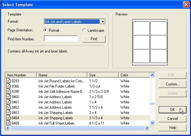
At the Select Template screen, choose the label you would like to use and click ‘OK’.
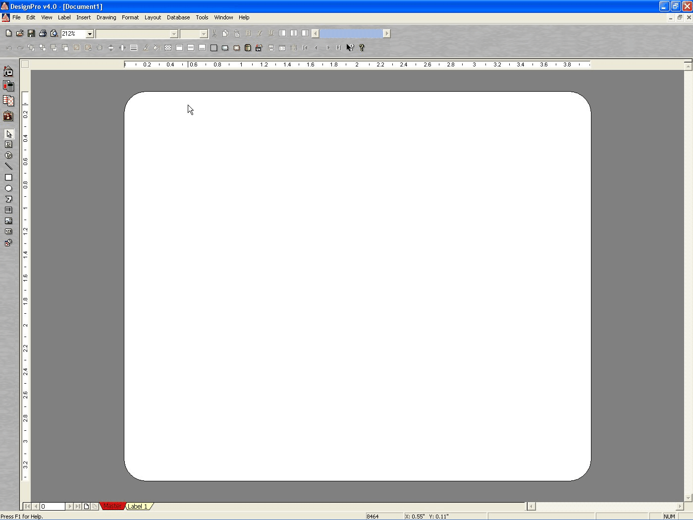
This screen shows actual label that you chose in the previous step.
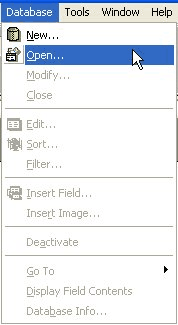
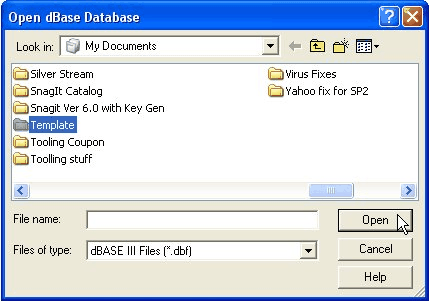
From the Database pull down menu, choose Open…
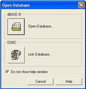
Click on the 'Open Database' icon. At this screen, go to the folder that you created at the very beginning that has the label.dbf
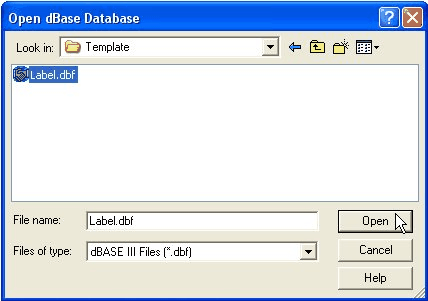
After opening the Template folder (or whatever you called it), select the label.dbf and click ‘Open’.
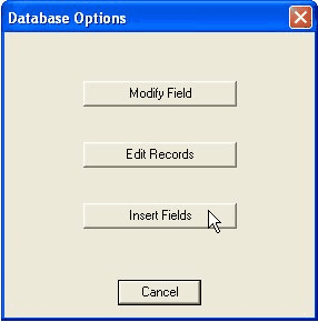
At the next screen, select ‘Insert Fields’.
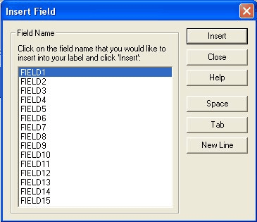
This will open the Insert Fields box.
The next few images will show Field descriptions.
Hw-417-v1.2 Driver FixedWindows 10 and 11 occasionally download this driver via Windows Update, but manual installation guarantees stability. Go to System Settings > Privacy & Security . Scroll down to find a message stating system software from developer "Jiangsu Qinheng Co., Ltd." was blocked. Click Allow . Restart your Mac. Verifying macOS Installation: : Official FTDI drivers occasionally block or "brick" counterfeit chips (showing a "non-genuine" error or a "Code 10" in Device Manager). : The ESP32 runs at 3.3V logic, while many HW-417-V1.2 boards require 5V logic. Use a logic level converter or buy a 3.3V-compatible tilt sensor. The HW-417 V1.2 is a widely used USB-to-TTL serial adapter board. It allows your computer to communicate with microcontrollers, routers, and other serial devices. At the heart of this board is the CH340 serial converter chip. Once you have identified the text printed on the chip, use the corresponding guide below to install the correct driver. 1. WCH CH340 Series Driver (Most Common) hw-417-v1.2 driver Standard layout breaking out VCC, GND, TXD, RXD, RTS, and CTS In the past, certain chip manufacturers (most notably FTDI) released driver updates that intentionally bricked counterfeit chips. The operating system interface layer is implemented as a set of APIs that provide a interface to the operating system. The operating system interface layer APIs are designed to be operating system-dependent, requiring specific implementation for each operating system. Windows 10 and 11 occasionally download this driver The HW-417-V1.2 board relies on a specific USB-to-Serial bridge chip. Identifying this chip is the most critical step for driver installation. The Core Chip Dual-voltage logic support for 3.3V and 5.5V systems (controlled via an on-board jumper toggle)
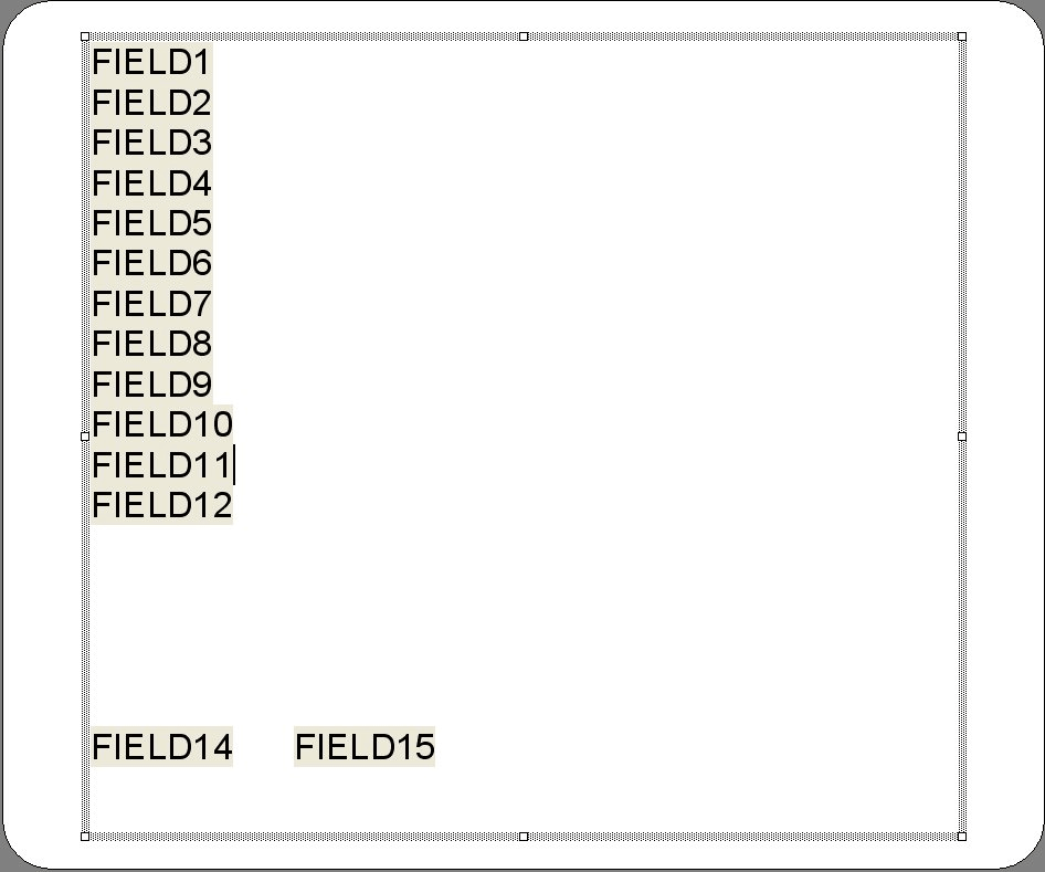
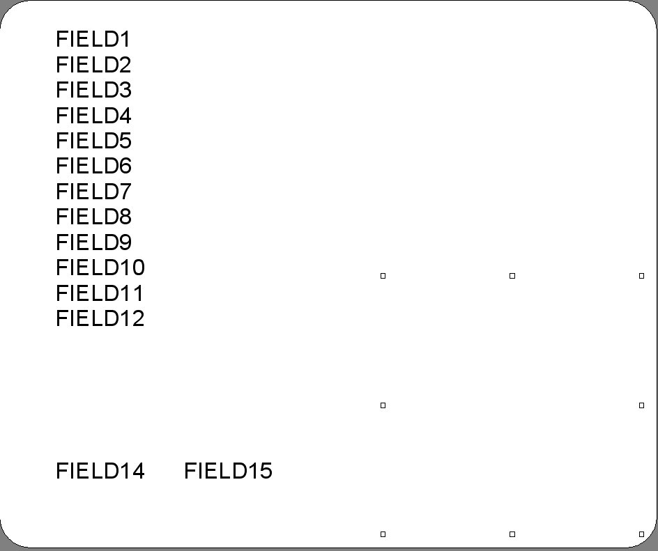
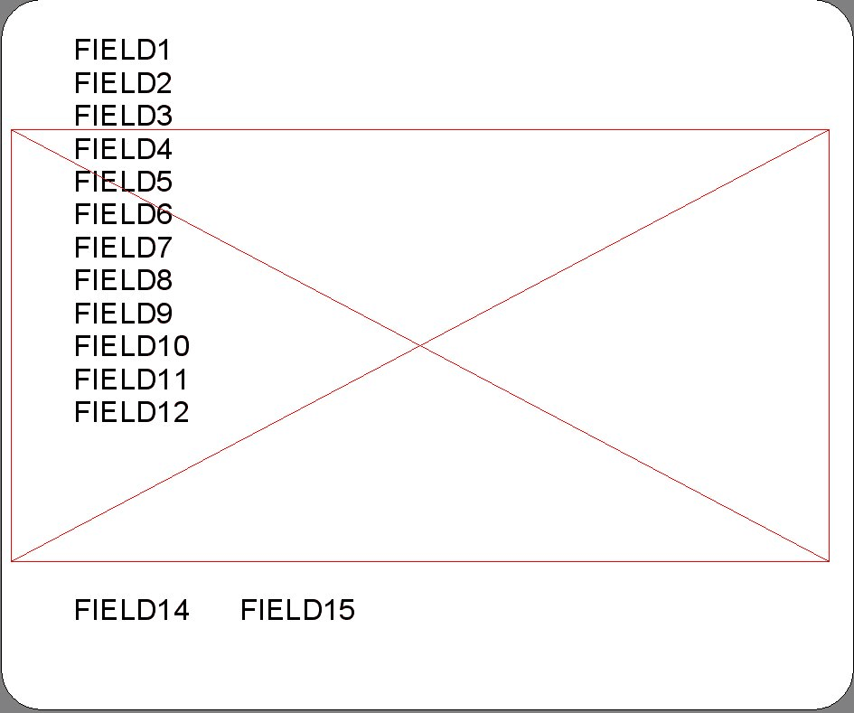
Using the Insert, Space, and New Line buttons, you can make the layout for you’re your new labels. Because of the size of this label, I was able to fit all of the fields on this label. Remember, the size of the label you choose dictates how much information (or how many fields) you can actually place on the label.
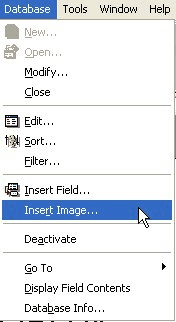
Notice the placement of fields 14 and 15. This will be important because placing it at the bottom of the label; these fields will be at the bottom of the Bar Code. Also notice that Field 13 is not on the label above. This is explained next… Field 13 is the graphic that can show the picture of your part on the label. To place a graphic on the label, from the Database pull down menu, choose ‘Insert Image’
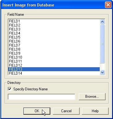
Choose Field 13 and click 'OK'.
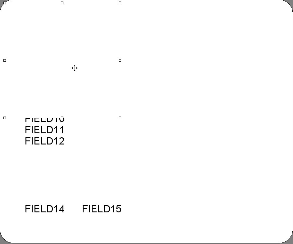
By default, the graphic is placed in the upper left corner of the label.
By grabbing and dragging, place the graphic box in the location you would like your graphic it be placed. For this example, I have placed the graphic in the lower right corner.
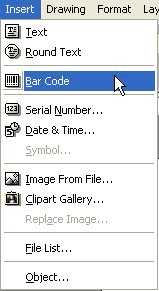
Field 15 is used to place a Bar Code graphic on the label. First, from the Insert pull down menu, choose ‘Bar Code’.
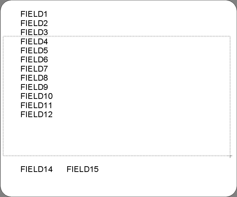
Your cursor will now change, drag from the upper left to the lower right to create a box.
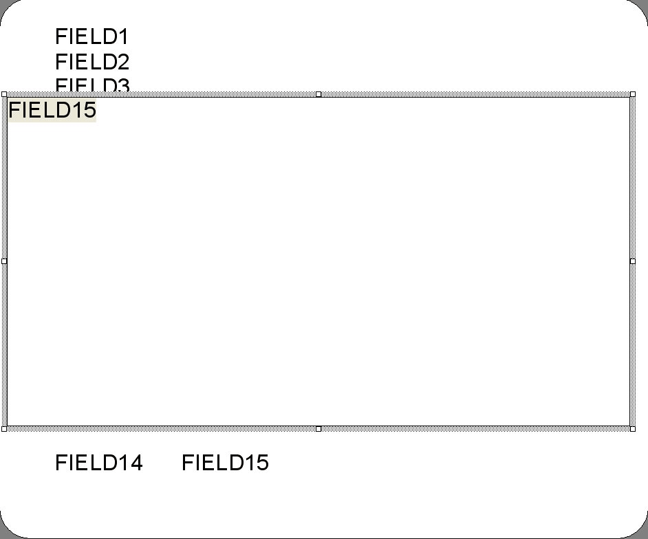
After the box is created, from the Database pull down menu, choose ‘Insert Fields’ and click on Field15 and click ‘Insert'.
When finished, your label should look like this.
NOTE: To prevent the bar code from becoming larger than the label and to have the name of the bar code shown, follow these steps: Highlight the bar code image and right-click on the dotted edge. Select 'Format Bar Code...' for the list.
This will open the Format Bar Code dialog box:
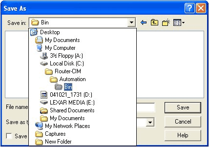
You want to make sure that 'Display Plaintext' and 'Adjust Size' are selected. Now it’s time to save your label. Choose 'Save’ or 'Save As’ from the file pull down menu. The Save in: should be set to C:\Router-CIM\Automation\Bin.
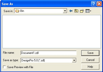
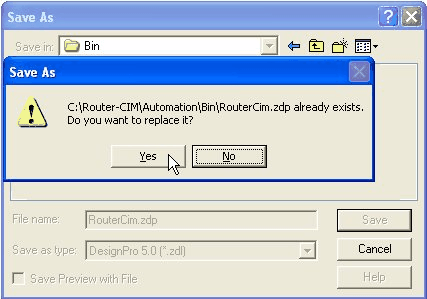
PLEASE NOTE THE FILE NAME: The only choice you have is to save it as a .zdl type at this point. In the File name: type in RouterCIM.zdp and click 'Save'. You should be asked if you would like to overwrite the file. Answer ‘Yes’
Copy the label.dbf file from the Template folder created in the beginning of the tutorial to the C:\Router-Cim\Automation\Bin folder and choose 'Yes' to overwrite the existing file. Then delete the copy of the label.dbf file in the Template folder you created. You are finished….run a job through Automation. When the job if finished and you open the Data Folder, you will see a RouterCIM.zpd file. Double-click on it. You will probably have to set the path for windows to open this type of file. The application to use would be the Labeler.exe found in C:\Program Files\Avery Dennison\DesignPro 5.0 Limited Edition folder. |